|
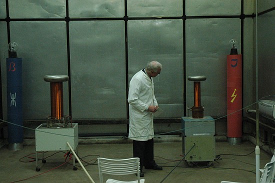
Housed in a former warehouse in Boeslunde near Slagelse, Denmark. Here you can see some of the Experimentarium's most spectacular objects. Drag the mouse over one of the five items in the illustration and left click to see more about Tesla coils, Jacob's Ladder, Mercury Rectifier and Marconi transmitter. You can e-mail Jens Aaløkke (OZ1GEO): radiosus@mail.dk
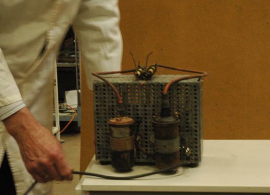
Mercury Rectifier
220
V DC OUTPUT 20 A
Mercury Rectifier (Photo: Mathias Dyhr, June 2008)
Mercury Rectifier (Photo: Mathias Dyhr, June 2008)
A mercury rectifier containing a pool of liquid mercury. The electrons ionizing the mercury vapor are emitted by a high temperature arc circulating on the surface of the pool. The quartz tube containing the 380 volts electrodes are bent 90o so no direct flash over can occur. The
tube contains a ‘dipper’ for starting the tube. The ‘dipper’ is
activated by an external electromagnet and only activated for start-up. Two
minor electrodes are used for pulling a few amps for keep-alive current
in case there is no load on the 220 V side. A
total of seven electrodes penetrate the quartz glass envelope. The unit contains load resistances and start-up circuit. VIEWS: 972
Jacob's Ladder
IGNITION
COIL POWERED
Two
ignition coils are driven in counter phase to produce ~50 kV. The
Jacob's Ladder is between two electrodes from an oil burner. The
repetition rate is 50 Hz. The
ignition coil is driven by condensator of 2 µF in series with a
thyristor. When the thyristor is turned on, when the power voltage is at
its peak of 311 V an oscillation with a natural frequency of approx 8
kHz is started (a bypass diode is provided for the thyristor). The high voltage secondary has the same natural frequency and an optimum high voltage is obtained.
VIEWS: 854
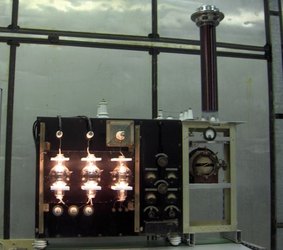
Marconi type transmitter
1
kW 500-3000 METERS TUBE
COMPARTMENT
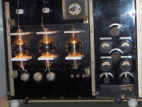
Marconi Type Transmitter
Closer look
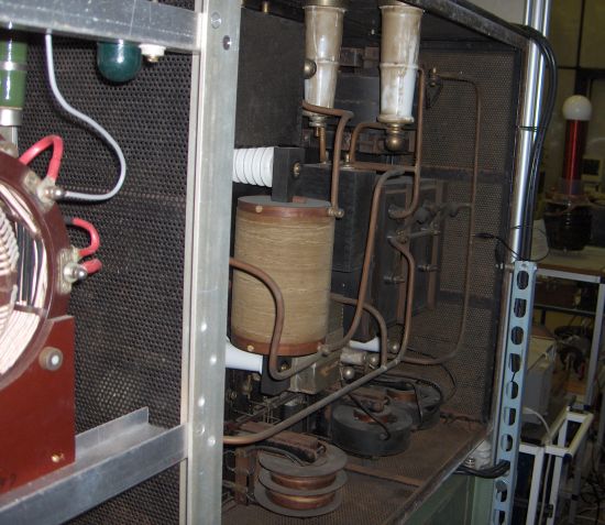
Rear side
The
unit has been used in a large Atlantic damper in the 1920’ths. The
tube compartment contains three Marconi tubes, two rectifiers and one
self oscillating power triode. Original 2 pcs MRO6 and a MT2B were
fitted. But as these are not available this unit is fitted with 2 pcs
MRO4 and a MT4B. They are slightly smaller tubes. The original tube
holders did not exist, so new substitutes are in place. The tubes are
heated from a 500 Hz, 500 W supply and the original anode supply of 12
kV has been reduced to a modest 5 kV powered by another 500 Hz, 300 W
supply in order to give 1000 Hz modulated CW transmissions. The
tuning unit was placed in the table and on the wall in the ships radio
room is not salvaged. A substitute coil from a M. P. Pedersen
transmitter from 1960 is used. The grid condenser is of the 10 kV type.
The antenna coil is the Tesla coil no.1, frequency of resonance in 660
kHz. The top hat is connected to the coil through neon glow lamps which
lights brilliantly during transmissions. The keying is done by a SSR in
the 500 Hz supply and relay contact in the cathode connection of the
tube. Power emitted 100-200 W.
VIEWS: 1015
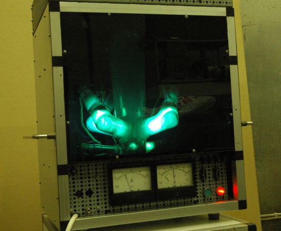
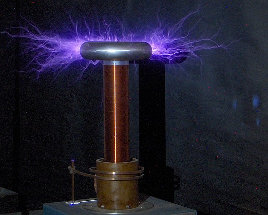
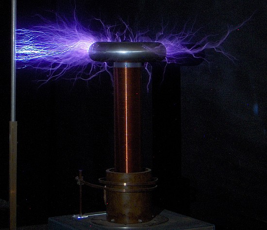
Tesla Coil No. 2
TORUS
Dy = 30 CM COIL
DIAMETER = 10 CM S PEAK
POWER 10 MW FRES 540 kHz
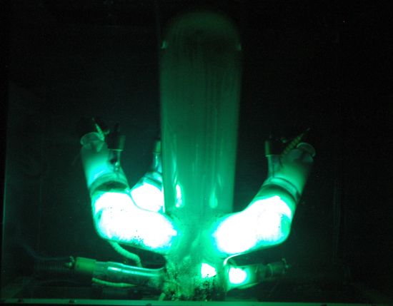
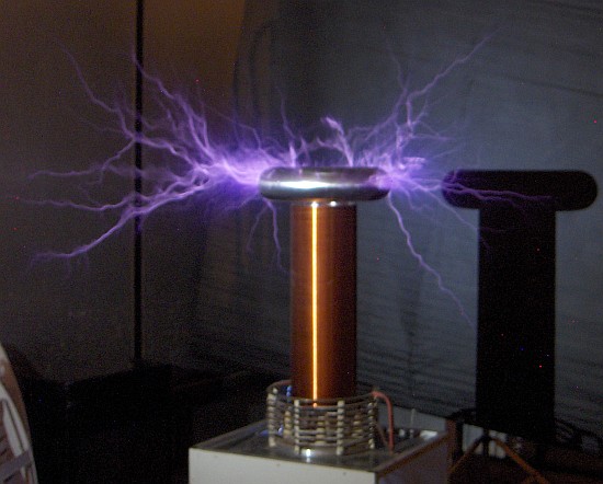
Tesla Coil No. 2. Peak power is 10 MW. This is a time lapse photo, so there are several discharges in this photograph
Tesla Coil No. 2. Discharges to a grounded rod. This is a time lapse photo, so there are several discharges in this photograph
Tesla Coil No. 2 Power
supplied by 6 pcs Oil burner trafos in a symmetrical set up. The
condensers in the primary circuit is very large e.g. 8 pcs 12.5 nF. As
consequence the primary coil consist of only 2 windings. The
peak power stored in the condenser is then very large as one should
think this will give a spectacular show, but that is not the case. The repetition rate is what gives the best spark length. Also provided a variac for adjustments of spark length.
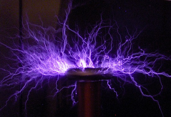
Largest Tesla Coil (No. 5) TORUS
Dy = 40 CM Spark
length 1.2 m PEAK
POWER 20 MW
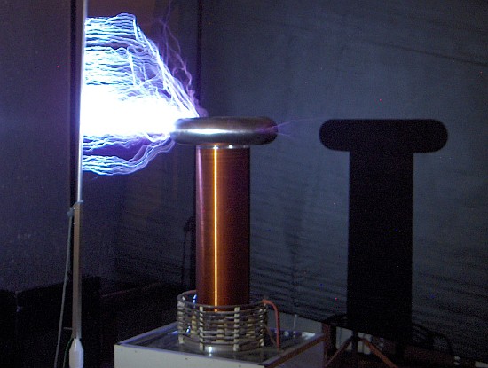
Traditional TC made by Jens Aaløkke 2002 (Tesla Coil No. 5). Spark length: 1.2 m (4 feet), peak power is 20 MW. This is a time lapse photo, so there are several discharges in this photograph
Tesla Coil No. 5. This is a time lapse photo, so there are several discharges in this photograph
Tesla Coil No. 5. Discharges to a grounded rod. This is a time lapse photo, so there are several discharges in this photograph
Tesla Coil No. 5 Traditional
TC with one layer coil on an 8” clear plastic tube. Wire
thickness 0.5 mm. Resonance frequency 500 kHz. Power supply made of 10
pcs Oil burner Ignition Trafos. In As
the spark gap is fixed higher settings of the variac gives not a higher
peak power, but a higher repetition rate – and only at this high rate
the wanted spectacular long lightning can be experienced.
Jens Aaløkke presents Tesla Coil No. 5 (left) and Tesla Coil No. 2 (right) (Photo: Mathias Dyhr, June, 2008)
VIEWS: 1076
Thank you for visiting this page
|
Vejret i Nyborg
kl. 15:12
Lufttemp.: 13,0 °C
Lufttryk: 1023,0 hPa = 767,3 mmHg
Luftfugtighed: 100 %
Nedbør: 0,0 mm
Vindstyrke: 1,5 m/s
Vindstød: 1,0 m/s
Næsten stille
Retning: 166° SSØ
Sol op: 05:43
Sol ned: 20:45

INDHOLD:
| Se landkort med de gamle
baner |
| (opdateret 2017) |
| Nyborg H/ Færgehavn |
| (jernbanenostalgi) |
| Knudshovedbanen |
| (jernbanenostalgi) |
| SNB Svendborg - Nyborgbanen |
| (jernbanenostalgi) |
| Hvad er der tilbage af
SNB?
|
| (jernbanenostalgi) |
| RNB Ringe - Nyborgbanen |
| (jernbanenostalgi) |
| Hvad er der tilbage af RNB? |
| (jernbanenostalgi) |
| OKMJ Odense - Kerteminde -
Martoftebanen |
| (jernbanenostalgi) |
| ONFJ Odense - Nr.Broby - Fåborg Jernbane
|
| (jernbanenostalgi) |
| De sidste færger på Storebælt |
| (tog/bilfærger og Vognmandsruten) |
| Tog i Nyborg |
| (video-clip) |
| Arkiv Ugens Togfoto |
| (gense tidligere foto) |
|
Stationssøgeren |
| (pop up vindue) |
| Jens
Aaløkke OZ1GEO Experimentarium |
| (Tesla coils etc.) |
| Tesla show 2007 |
| (den 25/10-07) |
| Jens Aaløkkes Samling/Collection |
| (oversigt over samling) |
| Ohms lov |
| (med regnemaskine) |
| Nyborgs største antennemast |
| (mobiltelefoni) |
| Besøg på TV-station Sdr. Højrup |
| (den 26/4-01) |
| Fyrtårnsweek-end |
| (Knudshoved 2001-02) |
| Info-siden |
| (mere vejr) |